Contract PCB Assembly Techniques
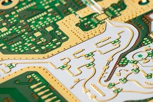
PCB assembly is a complex and time-consuming process. It requires meticulous attention and precision. A minor change in a single element can result in a huge difference in the final product quality and cost. It is thus imperative that customers evaluate and choose a reliable contract pcb manufacturer.
The first step in a contract pcb assembly process involves reviewing the design output files. These include Gerber, IPC 2581, and ODB++ files. They also contain schematics, assembly drawings, and BoMs. These files are necessary for a CM to perform a detailed and comprehensive review of the board’s construction and functionality. In addition, a DFM check (Design for Manufacturability) is conducted to ensure that there are no issues that can affect the board’s functionality.
Once the design files are reviewed and approved, the board is prepared for production. This includes etching, which is the process of removing copper from the substrate. The resulting material is used to create the circuitry on the surface of the board. In the next step, solder paste is applied to the surface of the board using a robotic device. The component pins are then positioned on the paste and then soldered using high-temperature heaters. Afterwards, the board is moved to cooler heaters where the solder solidifies and connects the components to the printed circuit board.

Contract PCB Assembly Techniques for Flexible Circuit Boards
Using flex circuit boards can save significant costs for manufacturers, particularly when it comes to space and weight reduction. For instance, a rigid-flex board can replace the need for multiple individual circuit boards and wire harnesses in a device, thereby reducing its overall weight and facilitating miniaturization. It can also reduce the risk of wiring errors, which are common causes of product failures in standard circuit boards.
Rigid flex circuit boards are ideal for use in applications that require both space-efficiency and high-vibration tolerance. They are also capable of providing a high level of thermal management, which can be achieved by minimizing the thickness of the copper planes and traces, increasing their width, and optimizing the trace lengths. Additionally, they can be designed to include stiffeners based on the specific requirements of an application’s mechanical and size constraints.
A flex circuit board can be made to incorporate all of its connections, eliminating the need for wire harnesses and connector pairs, which can reduce both labor costs and assembly time. In addition, incorporating the wiring directly into the flexible printed circuit board reduces assembly errors caused by connecting the incorrect wires. This can significantly reduce the number of defective products that are returned to customers. Moreover, the use of flex circuits can significantly cut down on production costs and improve overall product quality. However, it is important to note that flex circuits are not suitable for all applications. Therefore, it is essential to explore alternative designs like rigid-flex configurations before making a final decision.